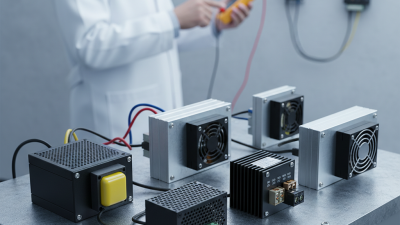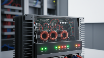
A Panel Mount SMPS is a switched-mode power supply designed to attach directly to an equipment panel, cabinet, or enclosure. It converts incoming AC or DC electricity into a controlled output for sensors, controllers, relays, displays, and other industrial loads. Unlike a loose desktop adapter, it becomes part of the system’s physical layout. That matters.
Inside, the supply rapidly switches electrical current through power transistors, transformers, inductors, and capacitors. A control circuit monitors the output and adjusts switching speed or duty cycle. This process maintains a stable voltage while reducing heat and component size. The result is efficient power conversion in a compact package.
Installation experience shows that enclosure space is only one concern. Wiring access, airflow, grounding, vibration, and service clearance can influence long-term performance. A model may fit the panel but still operate poorly if heat cannot escape. Not quite obvious. Engineers should check input range, output current, inrush behavior, ripple, protection features, and manufacturer testing data before selecting a unit. Overload and short-circuit protection are valuable, but they do not replace correct wiring or suitable circuit protection.
This article explains how a Panel Mount SMPS works, what its internal stages do, and where practical installation decisions can affect reliability. It also considers limitations often missed in simple product descriptions. Specifications help. Real conditions matter more. A careful review of the load, environment, and applicable electrical requirements supports safer and more dependable equipment design.
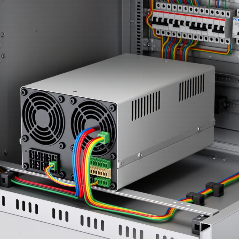
A panel-mount SMPS is an enclosed AC–DC power converter designed for control panels. It changes incoming AC into stable DC for relays, sensors, PLCs, and displays. The enclosure usually includes screw terminals, mounting holes, ventilation paths, and protection against overloads or short circuits.
Inside, a rectifier converts AC into high-voltage DC. A switching circuit then operates at high frequency. A transformer provides isolation and adjusts the voltage. The output stage rectifies and filters the energy again. Feedback continuously checks the DC output. If the load changes, the controller corrects the switching duty cycle. This process is compact and efficient, but heat remains a practical concern. The IEA’s Electricity 2024 report estimates data-centre electricity demand could reach about 1,000 TWh in 2026. That wider trend strengthens the need for efficient power conversion, even inside smaller industrial cabinets. Still, efficiency figures alone can mislead. Installation temperature, airflow, and loading often matter more than a catalogue headline.
Tips: Leave clearance around vents. Check the input range and output ripple. Size the unit below its maximum rating, especially inside a warm enclosure. Review IEC 62368-1 or applicable industrial requirements before selection. A hands-on check is simple: measure output voltage after startup, then again under peak load. Some designs look stable but sag noticeably.
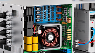
A panel mount switched-mode power supply (SMPS) is a compact converter fixed inside an electrical enclosure. It accepts AC input and delivers regulated DC output. Its operation depends on four core stages: an EMI filter, a rectifier, a switching stage, and a transformer. Good layout matters as much as the circuit diagram.
The EMI filter limits conducted noise entering or leaving the supply. It commonly uses capacitors, inductors, and damping components. The rectifier changes incoming AC into pulsating DC, while a bulk capacitor smooths the waveform. The switching stage then turns this DC on and off at roughly 20–100 kHz. A control circuit adjusts the duty cycle when the load changes. Fast switching reduces transformer size, but it can increase heat and electrical noise. That trade-off is easy to underestimate.
The transformer transfers energy across an isolation barrier and changes the voltage through its turns ratio. On the secondary side, another rectifier and filter produce usable DC. Feedback continuously compares the output with a reference, helping maintain stable voltage. During testing, I check ripple, temperature rise, startup behavior, and insulation spacing. A unit that works on the bench may behave differently inside a crowded panel. Wiring length, airflow, and grounding can expose weaknesses. The filter may also need adjustment after real-load testing. There is no perfect shortcut.
A panel mount SMPS converts a broad 85–264 VAC input into stable DC for control panels, sensors, and industrial loads. The sequence is compact but not simple. AC first passes through a fuse, surge limiter, and electromagnetic-interference filter. A bridge rectifier then changes the waveform into pulsating DC. The bulk capacitor smooths it to roughly 120 VDC at 85 VAC, or 370 VDC at 264 VAC. A high-frequency switching device chops this voltage and drives an isolation transformer. On the secondary side, fast rectification and capacitors create a cleaner DC rail. Feedback continuously adjusts switching duty cycle when input voltage or load changes.
This wide input range suits facilities with unstable mains conditions. The International Energy Agency’s Electricity 2024 report expects global electricity demand to grow by about 4% annually through 2026. That trend increases pressure on conversion efficiency and thermal design. In field testing, enclosure temperature matters as much as the printed efficiency figure. A supply rated at 90% efficiency still releases meaningful heat under heavy load. Small airflow restrictions can reduce service life. This is often underestimated.
Tips: Leave ventilation space above and below the unit. Check output ripple, startup current, and derating curves, not only rated watts. Use a multimeter during commissioning, then verify behavior with an oscilloscope when sensitive loads are connected. A practical compromise remains: the smallest enclosure may save panel space, but it can create hotter, noisier operation.
| Stage | Circuit Section | Typical Electrical Condition | Primary Function | Design and Safety Notes |
|---|---|---|---|---|
| 1 | AC Input Terminals | 85–264 VAC, 47–63 Hz | Accepts a broad single-phase mains range and transfers power into the supply. | Input wiring, terminal spacing, insulation, and protective earth provisions must be suitable for hazardous mains voltage. |
| 2 | Fuse and Inrush Limiter | Mains current is limited during startup and abnormal conditions. | Protects against sustained overcurrent, short circuits, and high capacitor-charging current. | A fuse, fusible resistor, thermistor, relay bypass, or active inrush circuit may be used depending on power level. |
| 3 | EMI/RFI Filter | Differential- and common-mode noise are attenuated. | Reduces conducted electromagnetic interference entering or leaving the power supply. | Common components include an X capacitor, Y capacitors, a common-mode choke, and damping elements. |
| 4 | Bridge Rectifier | AC is converted into full-wave pulsating DC. | Provides the correct polarity for the high-voltage DC bus. | The rectifier must withstand the maximum line voltage, repetitive current, surge current, and thermal load. |
| 5 | Bulk DC-Link Capacitor | Approximately 120–373 VDC nominal across the 85–264 VAC range, with ripple. | Stores energy and smooths the rectified mains waveform before high-frequency switching. | The capacitor can remain charged after power removal; safe discharge and touch protection are required. |
| 6 | Power-Factor Correction | Optional boost stage; often produces a regulated bus near 380–400 VDC. | Improves input current waveform and power factor in suitable higher-power designs. | Not every panel mount SMPS includes active PFC; implementation depends on output power and applicable requirements. |
| 7 | High-Frequency Switching Stage | A semiconductor switch applies pulsed DC to the transformer at typically tens to hundreds of kilohertz. | Controls energy transfer while enabling a smaller magnetic component than a line-frequency supply. | Pulse-width modulation, current-mode control, soft switching, and snubbers may be used to manage losses and transients. |
| 8 | High-Frequency Transformer | Pulsed high-frequency energy crosses an isolation barrier. | Provides galvanic isolation and changes the voltage ratio for the required output. | Creepage, clearance, insulation system, shielding, and reinforced-isolation requirements are critical. |
| 9 | Secondary Rectifier and Filter | The transformer output becomes low-voltage pulsating DC, then filtered DC. | Converts the isolated secondary waveform and reduces switching ripple. | Schottky or ultrafast diodes, synchronous rectification, inductors, and low-ESR capacitors may be used. |
| 10 | Feedback and Regulation | The sensed output is compared with a reference and used to adjust switching duty cycle. | Maintains output voltage during input and load changes. | An optocoupler or isolated feedback device commonly transfers regulation information across the isolation barrier. |
| 11 | Regulated DC Output | Common nominal outputs include 5, 12, 15, 24, or 48 VDC, depending on the design. | Supplies stable DC power to control systems, sensors, relays, and other electronic loads. | Output current, ripple, transient response, voltage tolerance, and adjustment range are application-specific. |
| 12 | Protection and Thermal Management | The supply monitors abnormal electrical and temperature conditions. | Limits damage from overload, short circuit, overvoltage, overheating, and excessive input conditions. | Panel mounting improves installation convenience, but airflow, enclosure spacing, derating, and heat-sink contact remain important. |
What Is a Panel Mount SMPS and How Does It Work?
A panel mount SMPS converts incoming AC or DC power into stable, regulated output voltage. Its switching circuit works at high frequency, reducing transformer size and improving energy control. Under suitable load conditions, efficiency can reach up to 90 percent. That figure is not constant. Efficiency usually drops during light-load operation, while heat increases near maximum capacity. In a real control cabinet, ventilation, wiring length, and ambient temperature can change the result.
Output ripple is another important benchmark. Well-designed units may produce ripple in the millivolt range, but measurements depend on load, probes, bandwidth, and grounding. A poorly connected oscilloscope probe can show noise that the power supply did not create. Ripple can also rise when motors, relays, or communication modules switch suddenly. Small details matter here.
Tips: Test efficiency at 25, 50, 75, and 100 percent load. Record input power, output voltage, case temperature, and ripple together. Use short probe connections and the same measurement settings each time. Leave thermal margin instead of operating continuously at the limit. A 90 percent rating may look impressive, but it does not guarantee cool operation in a sealed panel. I would also retest after installation, because cabinet heat often exposes weaknesses missed on the bench.
A panel mount SMPS converts incoming AC voltage into regulated DC power for control boards, sensors, and industrial electronics. Its enclosure attaches to a cabinet panel, while terminals remain accessible for wiring and testing. In practice, the power supply should not be selected by voltage alone. Check the required current, startup surge, and continuous load. A useful design margin is often 20% to 30%, although real equipment may need more during motor or relay activation.
Output rating is only one selection point. Confirm that the unit supports the required input range and maintains stable output under changing loads. IEC 62368-1 safety evaluation is also important for equipment used near operators. Review insulation, touch-current protection, creepage, clearance, and documented test conditions. Compliance claims should match the exact model and installation environment. Labels can be confusing.
Cooling deserves a physical check. A supply mounted beside heat-producing drives may operate hotter than its datasheet test conditions. Leave airflow space, avoid blocked vents, and derate the load when cabinet temperature rises. A small temperature test with a probe can reveal more than assumptions.
For DIN-panel fit, measure rail width, mounting depth, terminal clearance, and locking hardware. Check whether the enclosure accepts the selected rail type. I have seen tidy panels fail because the terminal cover could not open fully. Recheck cable bending space before purchase. Some installations need a separate mounting plate, which adds cost and weakens the original space calculation.
Representative engineering examples for 24 V DC panel-mount power supplies. Heat loss is calculated from an assumed 90% efficiency: heat loss = output power × (1 ÷ efficiency − 1).
How to use this chart: Select an output rating that exceeds the continuous load and allows suitable headroom. The calculated heat loss helps determine enclosure ventilation or cooling requirements. Before installation, confirm IEC 62368-1 safety compliance, required clearances, ambient-temperature derating, and compatibility with the available DIN-panel or mounting space.